EDA Component Libraries.
A CAD-neutral solution using a META data set
C.2008 Martin Macrae
INTRODUCTION
The most typical comment made by CAD users is that adding and maintaining the component library is the most time consuming and tedious task. The META system is designed specifically to solve this problem. Because it is not linked to any particular cad-system the component data-model used for META-data is designed to match the data source and entry system.
The Internet provides a useful source of component information, but the data is unvalidated and not in any particular CAD-system format. The META system is orientated towards using files and data obtained from the internet in a concise and readable form, which compared with present systems that have CAD-data models
These functions are achieved by the following :
Maintain the part-data separate from its CAD implementation format
In order to do this librarian task will change from symbol-drawing, drafting and mapping, to validating and filtering data. Priority shifts from creating data to managing data that may have been input elsewhere, So many users have indicated they need control over a number of CAD system libraries, so managing the changes and controlling the versioning and distribution of data becomes a significant portion of the librarians task, META data is optimized for that rhole.
Having a neutral format that can be implemented at any physical location has also become a requirement as companies want to prototype, and production manufacture in different countries.
Nevertheless , such a system must be easy to use and have data that can be easily read, updated and managed.
The majority of new components used in designs consist of large processor, memory and programmable devices, these do not have swapping gates or pins. The need for discrete logic has decreased in proportion, so the need to create many parts with swappable pins or gates is no longer the main requirement for component tools. Designs have many very large devices, and the success of routing layout would not be critically affected if there were no swapping of gates or pins. A larger amount of design effort is devoted to verifying signal integrity, electrical rules instead of optimizing routing.
Where preliminary released part-information is available on the internet, as a data-sheet or model file, much of its schematic and package information is different from the users requirements. The signal -name listings however, are often used directly to name the connection points, as they are needed to be known by electrical as well as layout engineers. The librarian will have a company preferred standard for drawing, this can be 'procedurised' as a 'generating program', used by both a librarian and any engineer to make prototype component representations. This can reduced or eliminate the 'librarian bottleneck'.
Generators are an efficient way of making very-large pin count package representations and schematic symbols. Since most parts are now packaged in regular-shaped packages, these lend themselves to auto-generation. The international schematic standard (IEE/ANSI/IEC) can be used to define the functions of the symbol generator
Many companies purchase fragments of their CAD/ EDA systems without thinking too much about how the data is to be kept consistent across all the different databases and applications. However, creating data from a point source, where it is also managed, is a method to prevent errors between different users further along the design process. META Template management software, in contrast, produces its own tracking information from s single source to manage change control. These traverse links to populate CAD databases downstream and update them as required.
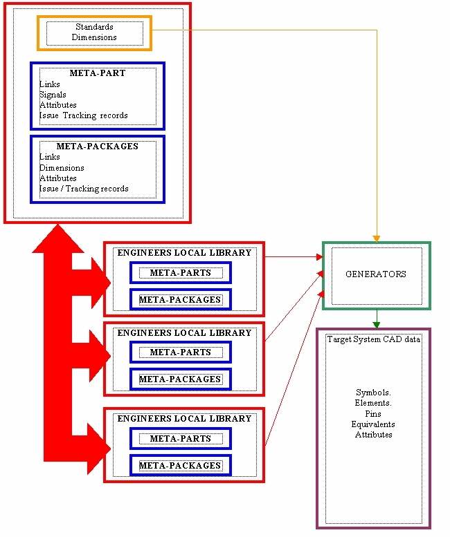
Since a company librarian will already have defined the company part-drafting standards, there is no reason why the company engineer cannot use data-building tools that are constrained by those rules to make local component representations as they require them, submitting the META-data for master-database re-use via the librarians control. This eliminates the Prototype/Librarian bottleneck while enforcing standards. Later on, as the design passes various control points, the authorized and validated representation can be substituted.
An established company master ECAD library may contain as much as 90% "legacy" data- That is representations that are no longer used for current designs but are maintained in the library in case an old design in reworked. Other part are kept as examples that would be copied and modified to make new parts symbols etc. Quite often a master library has to be migrated and translated to newer cad systems, where some of the usefulness of the data is lost in the translation. These two problems: maintaining legacy data and migration, currently take up much expensive effort. META-data is designed to ease these problems.
BASIC CONCEPTS OF META-DATA
Principal META-data tool Functional priorities
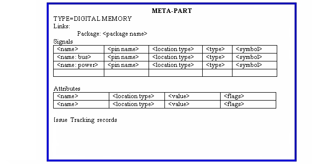
Within a META-data system. only the minimum, concise data is maintained. A SAMPLE Component Signal File The co-ordinates of the exact positions of every schematic symbol detail, for example, is not needed to be stored witin a META componenet library system.
The data is expressed in the target-system application format when required EXAMPLE of how a generator makes a symbol the user does not maintain the application format version of the data.
A META-data system is prioritized on making the very-large pin-count parts that are now predominant in designs. Templates for smaller gate/pin swapping parts are also provided.
Large-pin count parts are usually distinct, (not sharing data with other parts, other than the package). Thus there are only PARTS and PACKAGES to be maintained as separate items.
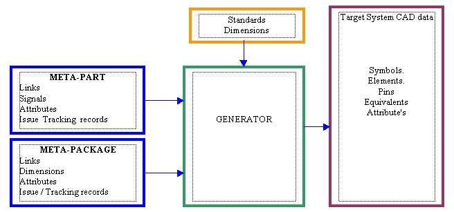
Within a data-management system incorporating META-data, the original data is filtered and merged with the company standards to produce META data.
The Validation and Filtering stage checks the data for consistency and applies keywords and tracking information.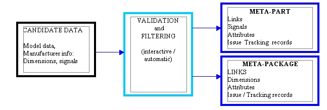
Now the META-data is combined with standards in a generator to make CAD data Here is an illustration of a data-management system using META-data to handle the design of prototype and production part representations. The META-data would be exchanged as ASCII files in file-browsers, between librarians and engineers. The META- Items could be different version of the same representations denoting prototype, pre-production and final design. Automatic systems would check back with the Master Library to ensure final designs had the correct version.
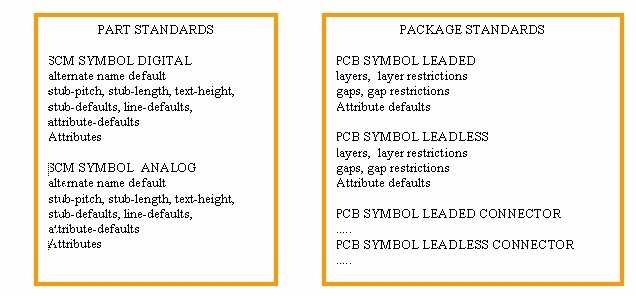
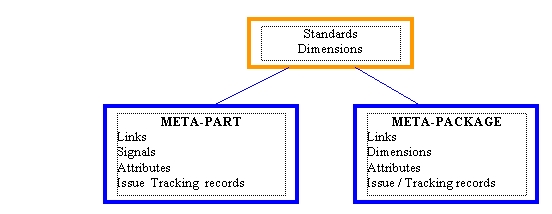
A META-data system would have to produce data for a number of CAD/CAE systems. Since software tools to make internet/intranet applications have progressed quickly recently, to a fairly common convention the GUI/File handlers for META-data would follow those styles instead of any specific CAD system. All META data is textual and can be stored in files. META-data has levels of conciseness depending on its source, Typically it occupies 1/1000th the size of a CAD-system specific file, as it does not contain drawing items or maps. META-data is in human-readable form within its own browser. Here are some examples of META-data. Standards, Dimensions
The META data definition is sufficiently small enough that it can be copied to the target library as part/package and pin attributes within the target library data-model. An existing Target system that does not have a META description for a part could have some data added to. Example: Part Templates : Package Templates Digital/IEE/IEC/ANSI Analog Leaded In-Line Circular Can Digital (square symbol) Amplifier/Comparator LCC/PLCC Connector Digital, -sub-gates Discrete, Range BGA Mechanical Digital Processor Discrete Multiple Discrete, 2-Pin, leadless Other, Generic Digital memory Transistor Discrete, 2-pin, leaded Junction device Each template family would have a number of options or variants. For example, The Discrete-2 pin package template would have Capacitor, Diode and resistor variants. END